Executive Engineering Summary
Cavitation is universally regarded as the most destructive physical phenomenon encountered in industrial centrifugal pump operations. Left unchecked, cavitation produces catastrophic pitting erosion across impeller vanes, violent acoustic vibration signatures, mechanical seal face shattered fractures, and severe hydraulic performance breakdown. Maintaining an adequate Net Positive Suction Head (NPSH) margin is not merely an operational recommendation—it is a mandatory thermodynamic design criterion.
1. The Microscopic Physics of Cavitation Nucleation & Implosion
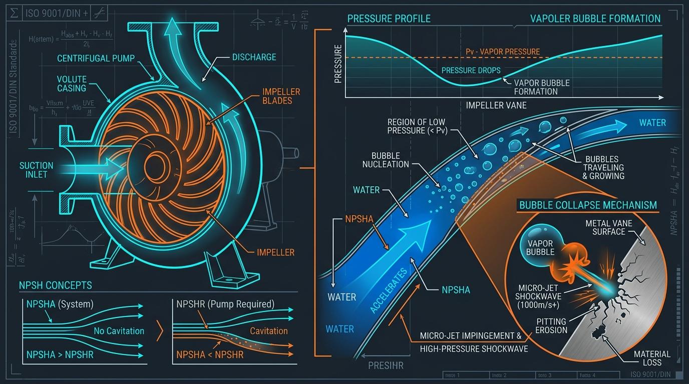
Classical cavitation is not boiling caused by high heat addition; rather, it is sub-atmospheric vaporization induced by hydrodynamic acceleration. As liquid enters the suction eye of an impeller, it accelerates over the leading edge of the vanes. By Bernoulli’s principle, fluid acceleration causes a localized dip in static pressure.
Phase 1: Vapor Bubble Nucleation
Whenever local static pressure drops below the saturation vapor pressure ($P_local < P_v(T)$), microscopic entrained gas nuclei rapidly expand into spherical water vapor cavities.
Phase 2: Cavity Sweeping & Pressure Recovery
The liquid flow sweeps the vapor clouds along the impeller blade passage into regions of rising static pressure generated by centrifugal work.
Phase 3: Asymmetric Micro-Jet Implosion
Vapor bubbles collapse violently within nanoseconds. Near blade surfaces, the collapse becomes asymmetric, firing a supersonic liquid micro-jet (>1,000 m/s) with localized impact pressures topping 10,000 bar (145,000 psi).
2. Formulating Net Positive Suction Head Available (NPSHa)
NPSHa is a property of the mechanical piping system and thermal operating environment. It represents the total absolute stagnation head above vapor pressure available at the pump suction nozzle centerline:
Where the essential parameters are defined as:
- P_suction_abs: Absolute pressure on the liquid surface in the suction tank (atmospheric pressure for open tanks; vessel saturation pressure for deaerators or closed receivers).
- P_vapor(T): Fluid saturation vapor pressure at operating temperature, computed via IAPWS-IF97 steam formulations or Antoine equations.
- Z_static: Net static elevation between the minimum liquid level in the suction tank and the pump impeller suction centerline (positive if tank is above pump; negative for suction lift).
- h_f_suction: Cumulative friction and minor fitting head loss across the entire suction run, including isolation valves, reducers, and strainers.
The Saturated Tank / Deaerator Paradox
In pressurized boiler deaerators, feed tanks, and boiling liquid receivers, water exists in thermodynamic saturation equilibrium (P_suction = P_vapor). Consequently, the pressure term (P_suction - P_vapor) / (ρ · g) evaluates to exactly zero! In such systems, the only positive driving head protecting the pump against catastrophic cavitation is the physical elevation column (Z_static) minus suction pipe friction (h_f_suction).
3. Demystifying NPSHr: The 3% Head Drop Testing Standard
NPSHr (NPSH Required) is an intrinsic characteristic of the pump hydraulic geometry established during shop testing per Hydraulic Institute ANSI/HI 9.6.1 or ISO 9906.
The Dangerous Myth of NPSH₃ (3% Head Falloff)
By international test standards, published catalog NPSHr is officially defined as NPSH₃—the suction head at which the total developed head of the first stage drops by 3.0% due to massive vapor blockages.
Critical Engineering Reality: Incipient cavitation (the onset of microscopic vapor bubbles and acoustic blade pitting) typically begins at suction head levels 2 to 4 times higher than published NPSH₃! Operating a pump with zero margin ($NPSHa = NPSHr$) does NOT mean zero cavitation—it means the pump is already in full cavitation breakdown.
4. Recommended Engineering Safety Margins per ANSI/HI 9.6.1
To ensure 40,000+ hour bearing and seal longevity and prevent acoustic erosion, the Hydraulic Institute mandates application-specific safety margins:
| Service Application | NPSH Margin Ratio (NPSHa / NPSHr) | Minimum Head Margin (NPSHa - NPSHr) | Reliability Target |
|---|---|---|---|
| High-Energy Boiler Feed & Nuclear | ≥ 1.35 to 2.00 | ≥ 1.5 to 3.0 m (5.0 to 10.0 ft) | Zero acoustic erosion; continuous 24/7 baseload utility |
| Chemical & Refinery Hydrocarbons (API 610) | ≥ 1.20 to 1.30 | ≥ 1.0 m (3.3 ft) | Bubble suppression per API 610 12th Ed specifications |
| General Commercial HVAC & Cooling Water | ≥ 1.15 to 1.20 | ≥ 0.6 m (2.0 ft) | Adequate for clean ambient water operating near BEP |
5. Suction Specific Speed (Nss) & Suction Recirculation
Pumps designed with oversized impeller eyes to advertise extremely low catalog NPSHr suffer a severe design compromise: high Suction Specific Speed ($N_ss$).
When $N_ss$ exceeds 11,000 (US units) or 215 (metric), the pump develops severe low-flow suction recirculation eddies whenever operated below 70% BEP. These vortices violently rotate backwards into the suction nozzle, causing cavitation-like hammering and high-frequency seal vibration even when NPSHa is exceptionally high.
6. Practical Industrial Worked Example
Problem: Deaerator Boiler Feedwater NPSHa Verification
A high-pressure boiler feed pump draws 32 m³/h from a pressurized deaerator operating at 1.8 bar gauge (2.813 bar abs) and saturation temperature 131.5°C (density ρ = 933.2 kg/m³). Suction liquid level is 4.8 meters above the pump centerline. The suction pipe (D = 100 mm) has a total friction head loss of 0.65 m (including entrance, gate valve, and strainer). The manufacturer specifies NPSHr = 3.2 m. Verify cavitation margins.
Frequently Asked Questions: Cavitation & Suction Hydraulics
What acoustic sound does a cavitating pump make?
A cavitating centrifugal pump typically sounds as though gravel, marbles, or broken glass are churning inside the impeller casing. This sound is caused by millions of micro-bubbles imploding against the interior casing and vane walls at supersonic shockwave velocities.
How does transient deaerator pressure decay cause catastrophic pump trips?
When an upstream steam turbine trips, the heating steam supplied to the deaerator stops abruptly, causing vessel pressure to plummet rapidly. However, the large water mass in the storage tank remains at the higher initial temperature. As pressure collapses faster than fluid temperature can cool, water in the suction pipe flashes instantaneously into steam vapor, vapor-locking the feed pump within seconds.
What is a suction inducer and how does it reduce NPSHr?
A suction inducer is an axial helical screw mounted directly ahead of the main centrifugal impeller eye. Rotating at pump speed, the inducer imparts a modest head rise (0.5 to 2.0 bar) directly into the fluid, suppressing bubble formation before liquid enters the main centrifugal vanes.